Posts: 4,443
Threads: 1
Joined: May 2015
Reputation:
204
(02-10-2018, 08:40 PM)Canard Wrote: Module order is A-D-C-E-B, with bogies in modules A, B, and C. Modules D and E are without wheels and supported by their neighbours. It is worth noting that this nomenclature is only valid for the 5-module variant; not the 3 or 7. In other words, you can't just benignly say "a C module is always a short, intermediate one with a bogie and no doors", because on the 3-module variant you'd have A-C-B, and C would be the same as a 5-module's D or E.
[....]
I don't think they will ever swap out a module on-site at Dutton. If a train gets hit by a car, and the damage is more than superficial, it'll likely go back to Bombardier for them to swap it out.
Thanks for the detailed information and photos. Much appreciated!
Posts: 4,443
Threads: 1
Joined: May 2015
Reputation:
204
(02-10-2018, 10:18 PM)tomh009 Wrote: Are D and E modules interchangeable? How about A and B?
I don’t know the full answer, but there has to be at least some small difference between D and E (and between the two ends of the C) because the C-D and C-E joints are different as mentioned in Canard’s post.
In principle they could put most 1-per-train equipment in the C module (and indeed, that is where the pantograph is) and 2-per-train in the other modules, but I have no idea how this is actually laid out. In fact, I know almost nothing in detail about what equipment is present beyond vague notions that there must be traction components, power handling, climate control, etc.
To a question somebody else asked about why there are only limited motions at the joints, if all the joints allowed pitch (up/down rotation) then the joints would not have a single defined arrangement to match any given track profile. The way it’s done, the C module can only exist in one pitch when the train is sitting on any given piece of track. Essentially the A-D-C/B-E-C (we don’t know which) modules form a bridge between the trucks on the A/B and C modules; then to keep the wheels on the B/A module on the track, it bends between the A-D-C/B-E-C and E-B/D-A modules.
I don’t know exactly what would happen in practice if there were more pitch joints, but seems to be considered desirable that the positions of the modules follow deterministically from the shape of the track. I’m guessing the C module would rock backward and forward unpredictably but I don’t know. Actually now I want to know what that would feel like to ride in. Probably not as smooth as the actual ride.
Posts: 6,905
Threads: 32
Joined: Oct 2014
Reputation:
224
02-11-2018, 07:43 AM
(This post was last modified: 02-11-2018, 07:44 AM by Canard.)
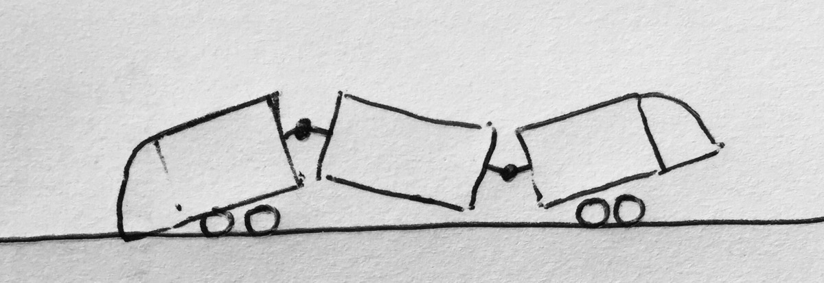
KevinL: that’s not why. Jamincan: The train would sag, and wouldn’t form a straight line on straight track. The system, kinematically, would be underconstrained. In other words, if you were a giant, you could reach down and twist and tip the train and it would stay in the pose you placed it in. That’s bad.
I have been trying on and off for a couple of years to make an animation for you guys (knowing this would come up and someone would ask eventually!) about why the trains are articulated the way they are. There is a bug in SolidWorks that prevents me from completing it (I have an SPR in...). I may just make a little model out of LEGO and a video for you instead. It’s immediately obvious why it’s configured the way it is if you can feel it with a model.
Posts: 2,004
Threads: 7
Joined: Sep 2014
Reputation:
125
I guess I can see why you wouldn't want any twist between the sections, or at least only one point that allows twist between the bogies, but I don't really understand the issue with pitch and yaw as I would have thought sections A-C-B were essentially fixed points relative to the track (in orientation and pitch).
Posts: 6,905
Threads: 32
Joined: Oct 2014
Reputation:
224
02-11-2018, 09:11 AM
(This post was last modified: 02-11-2018, 09:36 AM by Canard.)
That’s the thing - they’re not! The bogies can pitch. So, if they did what you suggest, the whole train could be a zig-zag if viewed from the side.

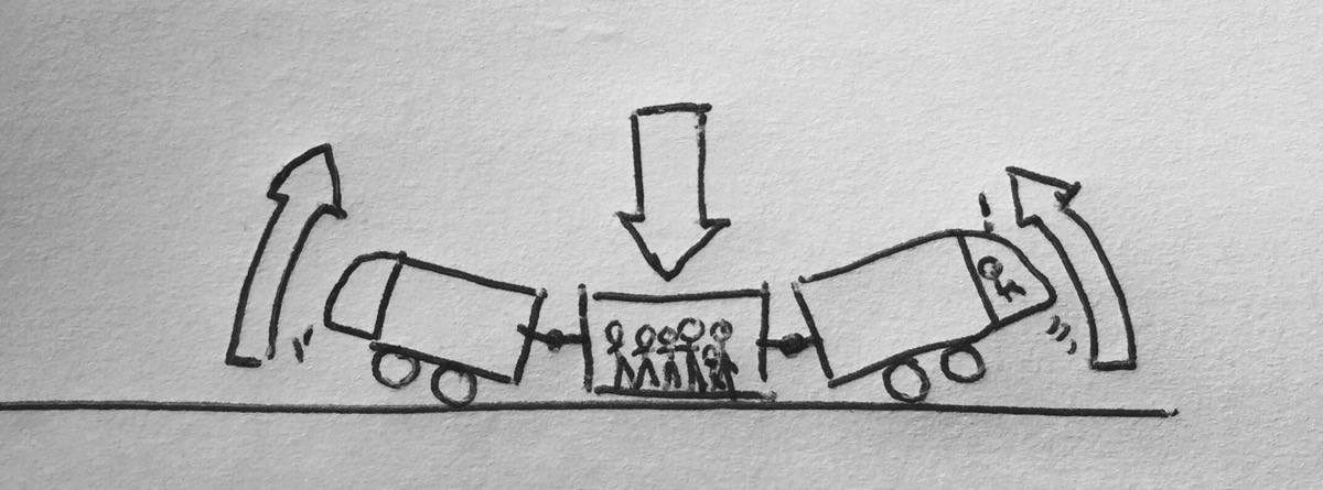
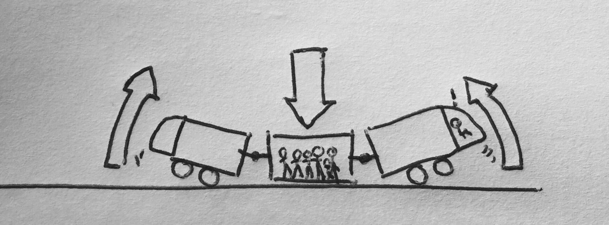
Even worse, even if the bogies truly were fixed axles directly mounted on the bogie frame, and we had pitch articulation between them, if the centre module were overloaded (say, by too many passengers), this would happen:

This configuration for fixed-bogie* trams is very obvious when viewing a 3-module LRV moving along track with a vertical curve, like the bridge in Kansas City right by Union Station. The whole LRV looks like a ridgid log when moving across it.
 *- a little bit of a misnomer, because, as I’ve explained, the bogies can pitch relative to the module, and even yaw just a little bit, to take up shock/jerk loads, if spiral curves are not used (ie, Toronto’s legacy network).
Posts: 2,004
Threads: 7
Joined: Sep 2014
Reputation:
125
Is the ability to pitch relative to the bogie simply an outcome of the suspension, or is it desirable for other reasons?
Posts: 6,905
Threads: 32
Joined: Oct 2014
Reputation:
224
02-11-2018, 09:34 AM
(This post was last modified: 02-11-2018, 09:35 AM by Canard.)
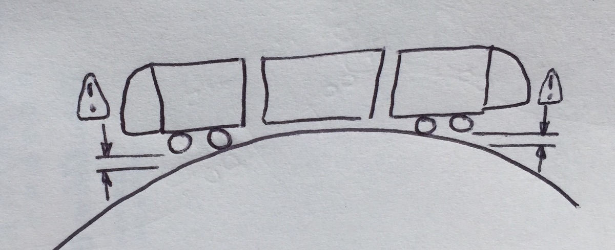
It is a requirement, and achieved via the suspension springs. If not, and the axles were ridgidly affixed to the module frame, this would happen:

(Trains would lift the leading and trailing axles when navigating a convex vertical curve)
Posts: 2,004
Threads: 7
Joined: Sep 2014
Reputation:
125
That wouldn't happen if they could pitch at the point of articulation, though.
With only two bogies, you might run into an issue where too much weight between the bogies could lead to the entire vehicle sagging and lifting the front/rear-most wheels off the track. I suppose they could balance the sections out to a degree to prevent this, but it might be possible that an uneven distribution of passengers could cause a problem.
Posts: 6,905
Threads: 32
Joined: Oct 2014
Reputation:
224
02-11-2018, 10:12 AM
(This post was last modified: 02-11-2018, 10:13 AM by Canard.)
Jamincan, my 2nd drawing in my 2nd last post illustrates exactly what you’re saying in your first paragraph, and why it won’t work. If the axles were fixed, and the vehicles could pitch between modules, you’d have a scenario where overloading the centre module causes a derailment.

Posts: 608
Threads: 0
Joined: Nov 2016
Reputation:
79
Love your drawings Iain!
...K
Posts: 6,905
Threads: 32
Joined: Oct 2014
Reputation:
224
Posts: 4,528
Threads: 16
Joined: Aug 2014
Reputation:
139
I see that the tracks downtown (and on Charles at least as far as Stirling) have had a particularly thorough snow-cleaning done. Hopefully good signs for a later appearance here...
Posts: 1,709
Threads: 2
Joined: Aug 2014
Reputation:
35
Whereas last night, the northbound tracks on Francis had several inches of hardpack and ice.
Posts: 619
Threads: 4
Joined: Jul 2016
Reputation:
22
Testing happening today all the way to King and Vic, potentially a bit further down, and tomorrow to Fairview!
Posts: 1,206
Threads: 0
Joined: Mar 2015
Reputation:
37
I saw a train heading south (on the northbound track) near Columbia Street this morning. Following up on my earlier comments, the gates were properly operating at the Columbia crossing.
|


